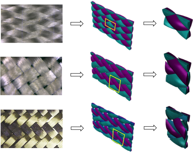
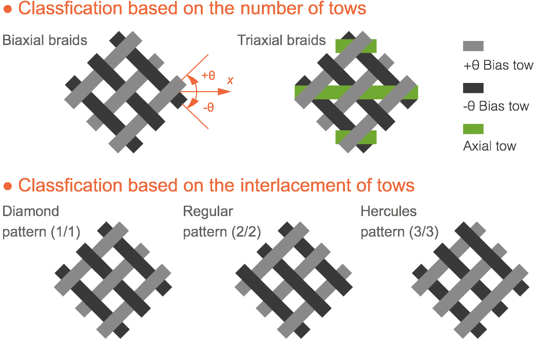
Depending on the number of composing tow sets, braids are commonly classified as biaxial braids with triaxial braids. Biaxial braids consist of a set of +θ bias tows and a set of -θ bias tows passing over and under each other. In addition to the bias tows, triaxial braids have a set of 0° axial tows inserted between the +θ and -θ bias tows.
Depending on the interlacement, braids are classified as diamond braid (1/1), regular braid (2/2), and Hercules braid (3/3). Diamond braids have an alternation of one tow passing above and then below the other tows (1/1), regular braids pass above two and below two tows in a repeat (2/2), and Hercules braids have a structure of three tows up and three tows down (3/3).
(1) Braiding angle —
(1) Braiding angle —
For diamond braids, one period of the undulation path is composed of two arcs which have the same radius. For regular and Hercules braids, in addition to the arcs, straight lines are inserted between the arcs.
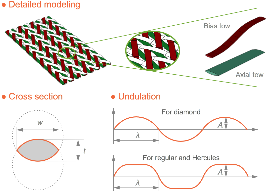
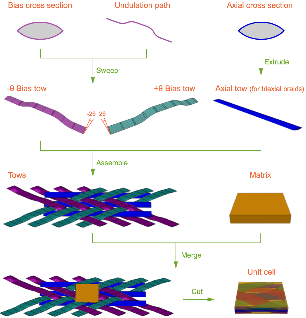
(1) The bias tow is modelled by a lenticular-shaped cross section sweeping along the undulation path. The axial tow is modelled by a lenticular-shaped cross section extruding along a straight line.
(2) During the sweeping process, the plane where the tow cross section locates and the plane where the undulation path locates form an angle which is twice as great as the braiding angle.
(3) Bias tows and axial tows are then arranged with the given braiding angle and a certain gap between tows.
(4) The matrix is modelled as a cube and then merged with the tows.
(5) Finally, the merged part is cut out of the arranged tows as a unit cell.
Note: The modelling procedure is generalized using the Python script for ABAQUS. Therefore, different models with different parameters can be generated instantly.
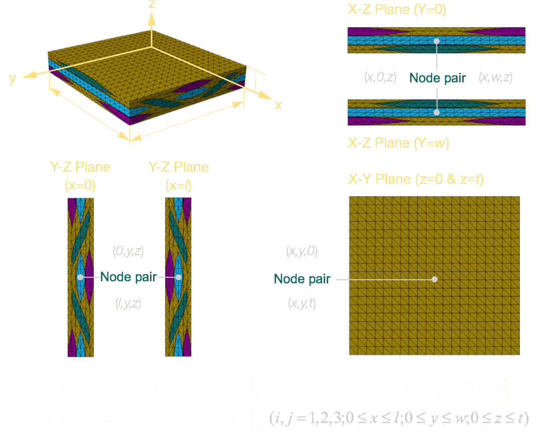
Since braided composites can be treated as a periodical array of unit cells, the periodical boundary conditions ought to be applied on the unit cell to ensure that there is no separation or overlap between the neighbouring cells. That is, the boundaries of one unit cell can match the boundaries of the adjacent cells prior to and after the deformation.
The right-sided figure demonstrates the three boundary pairs and node pairs. All the boundary pairs match each other exactly, which is a necessary condition for applying periodical boundary conditions. When generating the mesh, special attention should be paid on the node locations on all boundary pairs so that the node pairs can be found and constrained later by a third-party program. By applying the above periodical boundary conditions and using the equations, the constraints can be imposed on any arbitrary node pair.
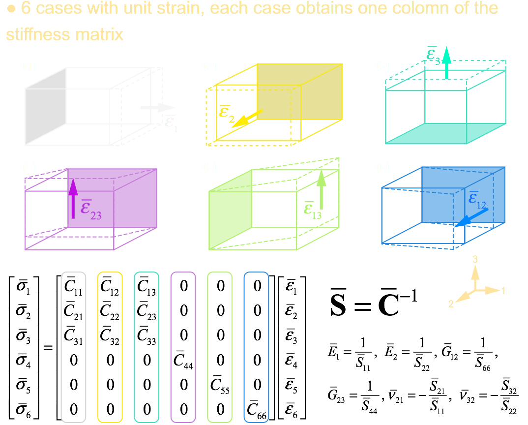
(1) 6 different cases are needed to be run, and each case will be assigned the above-mentioned periodical boundary conditions as well as a unit strain in a certain direction.
(2) The planes with solid color in the right-sided figure are fixed, while the dashed planes represent the deformed shapes of the unit cell.
(3) Each individual case gives one column of the stiffness matrix. In the figure, each diagram solves one column of the stiffness matrix which is marked by the box with same color as the diagram.
(4) After completing stiffness matrix, the compliance matrix can be obtained by inverting the stiffness matrix, from which all engineering constants can be computed.
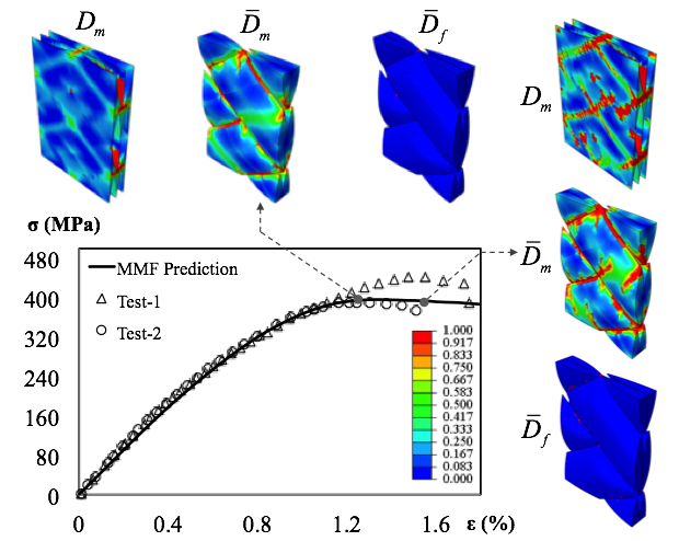
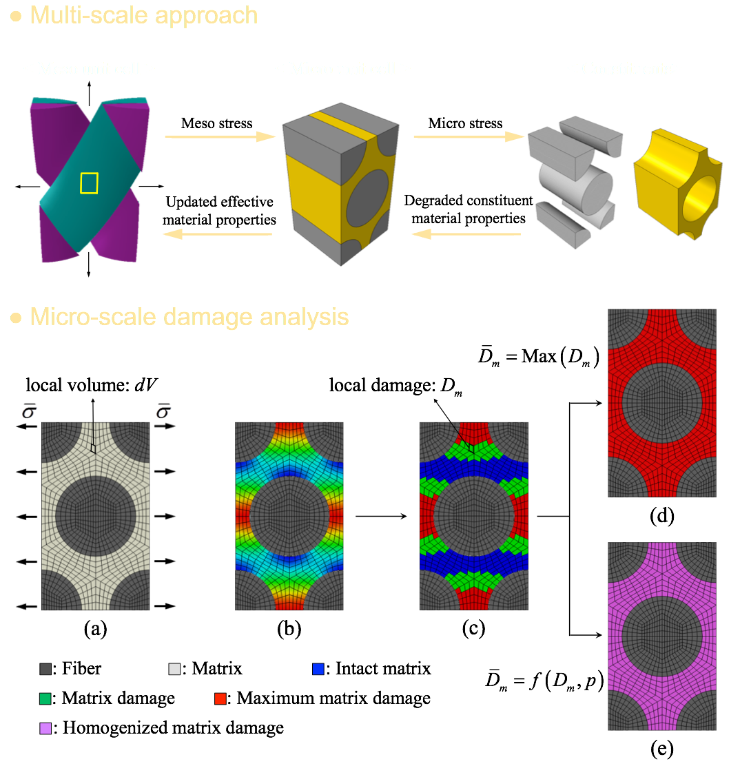
(1) In the multi-scale approach, data is transferred between the meso-scale and micro-scale models.
(2) The mesoscale structural analysis is used to inform the microscale unit cell model regarding mesoscale stresses and strains.
(3) The three-dimensional micro-scale unit cell model used in the MMF theory provides fully three-dimensional multi-axial micro stresses for each constituent.
(4) The damages to different constituents were distinguished based on each constituent damage model.
(5) In order to obtain the overall damage of each constituent, maximum damage method and damage homogenization method are adopted for different constituents.
(6) The effective material properties of tows in the mesoscale unit cell were recalculated from the microscale unit cell model with degraded constituent material properties.
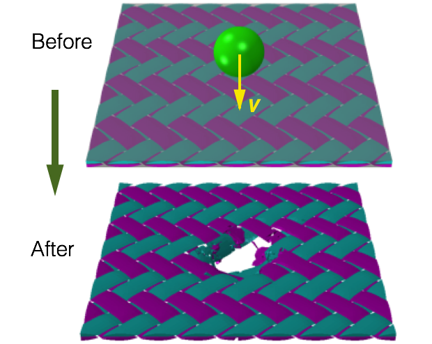
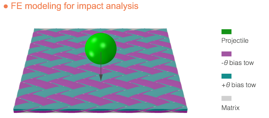
(1) The whole piece of braided fabric is modeled by linearly repeating the unit cell models in both x- and y- direcions.
(2) The contact properties between the projectile and the fabric are defined.
(3) Damage criteria are defined for pure matrix, and matrix and fiber in tows.
(4) Element deletion criteria are defined for both matrix and tows.
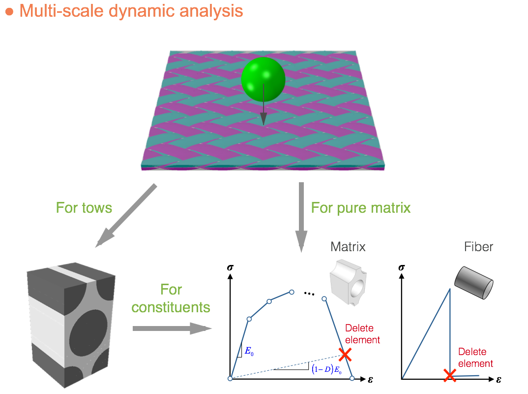
(1) The multi-linear damage model and the sudden failure model for both matrix and fiber are defined.
(2) The mechanical behavior of the tow is analyzed by the micro unit cell model.
(3) The mechanical behavior of the pure matrix is directly analyzed using the matrix damage model
(4) The stiffness of each element is progressively degraded based on the damage model.
(5) The element is deleted once the stiffness redcution meets the element deletion criterion.
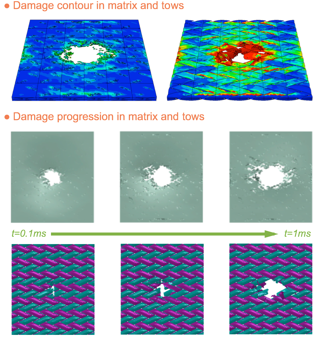
(1) The damage contour in both matrix and tows are plotted. In the tow, both matrix and fiber damage contours can be plotted.
(2) The element deletion history in both pure matrix and tows are plotted with respect to the impacting time.
(3) The pure matrix exhibits much severer element deletion than tows, which is obvious due to their respective properties.
(4) The damages in the pure matrix spreads in the entire braided fabric due to the impact energy transmission.
(5) The damages in the tows localize in the hitting region and hardly spread to other regions.
Note: This multi-scale approach can be applied for the dynamic impact analyses of various types of fabric composites such as woven fabric composites, non-crimp fabrics, short fiber composites, and etc.